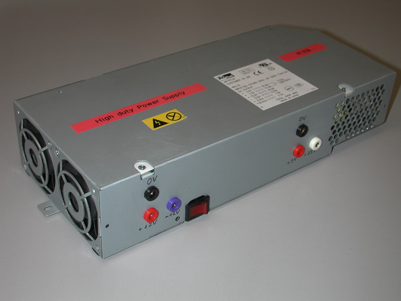
I needed a laboratory power supply that gives me a lot of power (more than 100W) at stabilized 12V. A spare computer power supply is a good and very cheap solution. On the net I found two pages that helped me with the conversion:
- Ian converted a G4 power supply to an ATX one, and
- Andy Batts converted
an ATX power supply to a laboratory one.
| Dual G4 Mac power supply (Mirrored Drive Doors) |
||||||||||||||||||||||||||||||||||||||||||||||||||||||||||||||||||||||||||||||||||||||||||||||||||||||||||||||||||||||||||||||||||||||||||
|
||||||||||||||||||||||||||||||||||||||||||||||||||||||||||||||||||||||||||||||||||||||||||||||||||||||||||||||||||||||||||||||||||||||||||

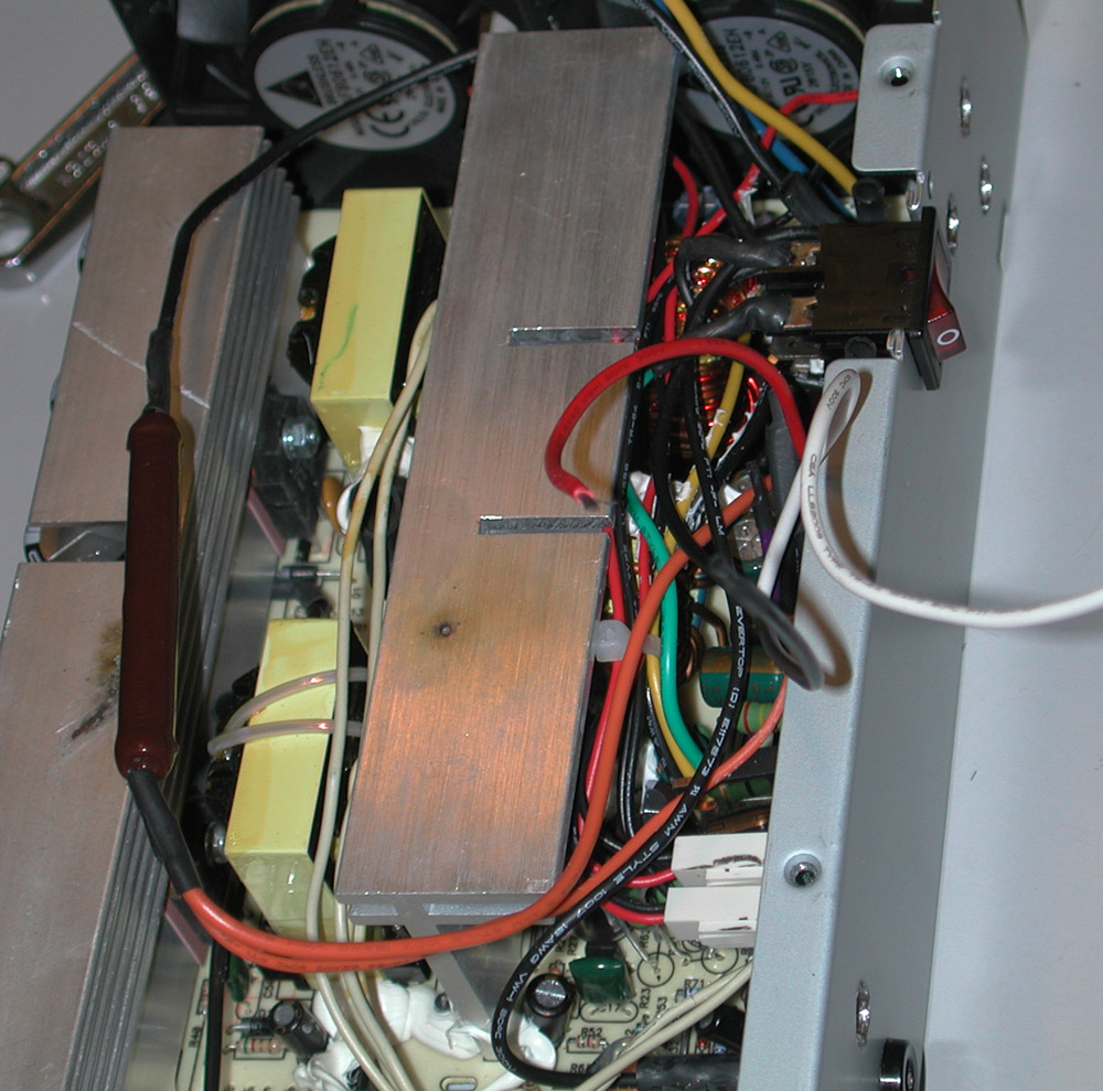
So let's start the convertion. Take the power supply and open it. Attention: the central large cooling plate is at 130V, if you let the plug in. You see the dirty spots on the two cooling plates on the photo? After touching one accidentally with my hand, I could not believe it that they let such a big cooler under voltage, so I connected it to the other cooling plate with a copper wire of tiny diameter. You see part of the effecs on the photo; it made a big flash, bang, the copper wire sublimated and kicked out the fuses of the whole room.
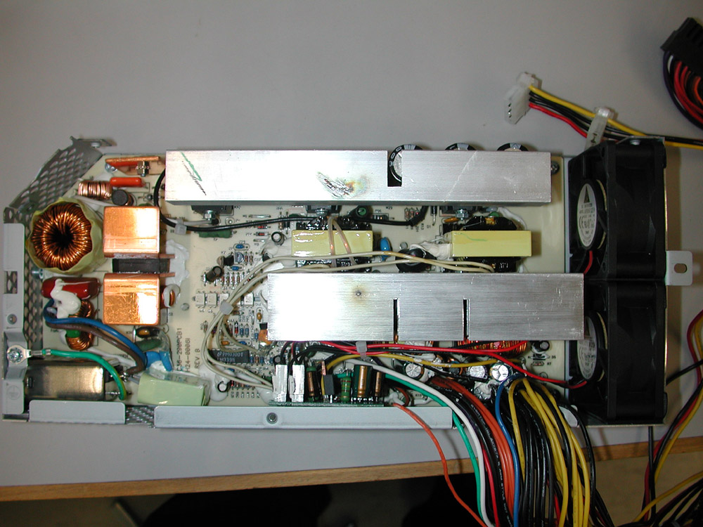
You can turn on the power supply by
connecting the green cable (PwrOn) to ground (one of the black cables).
But the power supply will immediately go to stand-by, leaving only pin 1
(+5Vsb) and pin 14 (+25Vsb) under voltage. To get full power you need
to have a minimum load of approximately 300 mW at pin 6 (+3.3V sense),
thus we will put a resistor there. So now that you know how to get it to
work, let's do it.
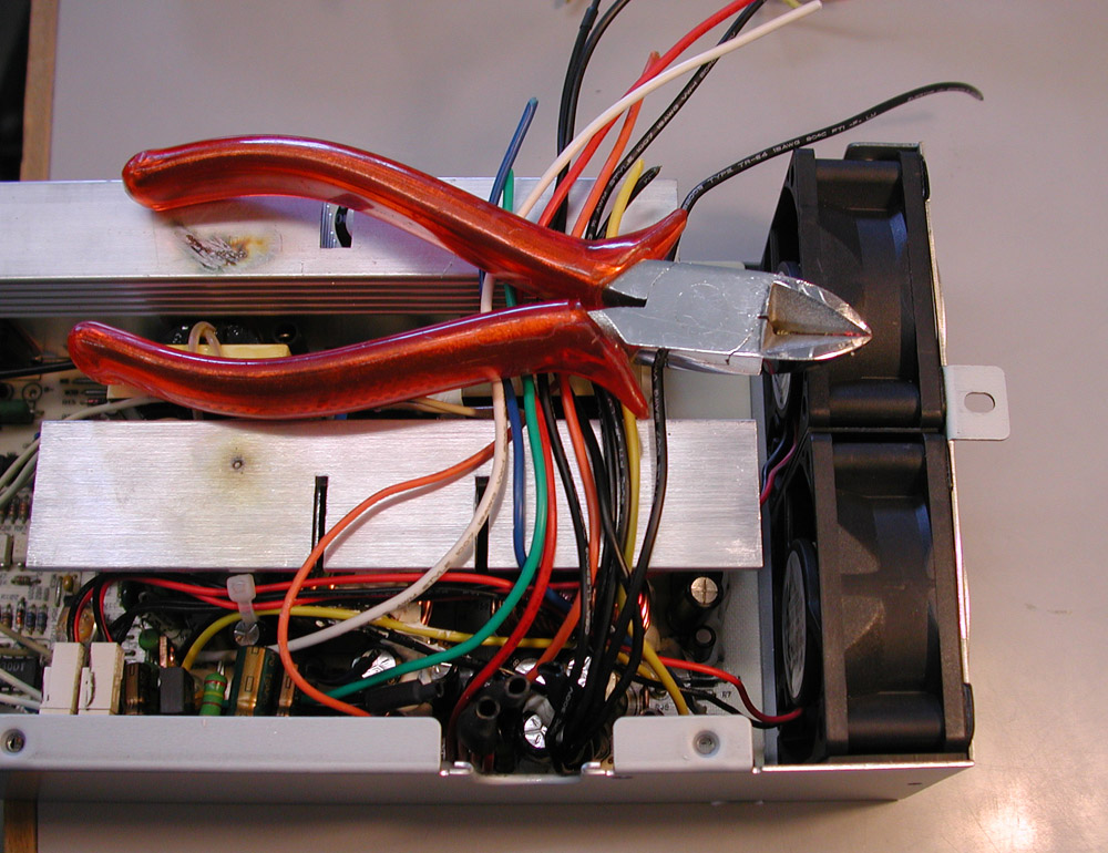
Cut away all the wires that you don't intend to use. I want 12V and since it's there, also -12V, 5V and 25V. So I need a yellow, blue, red and a white wire, 2 black ones for the ground, plus for turning the power on, the green and a black, and an orange, the thin orange and another black one. The rest I cut and isolate with shrinking tubes. By the way beware of the condensators on board: I found out when I asked a friend to hold two wires for soldering (the plug was of course off) and suddently got a horrible elbow punch on my nose! At least he got the electrical shock!
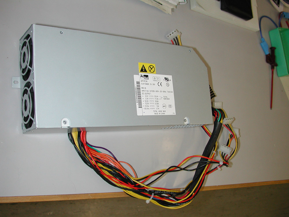
Between the green cable and a ground cable put the ON/OFF switch, you will surely find one that fits perfectly in the now unused cable hole in the case. On the other hand you will not find that much place for placing the output voltage jacks. I had to take out a fan to screw in the 12V jack. For drilling holes in the case you best close it, and then give your best at taking out all the swarfs from the drilling. Connect the 3.3V sense (normal orange and thin orange cable) to ground over a resistor of 10 to 30 Ohm that can bear the generated thermal power (e.g. for R = 30 Ohm: P = V2/R = 300 mW). Such wire wound load resistors can be found in old drawers in the laboratory or for 50 cent at electronics shops. You can connect the others cables to the corresponding output jacks. It's done, you have a stabilized power supply with the following maximal currents:
| Voltage |
Max. Current |
Max. Power |
|---|---|---|
| +3.3V | 17A |
56W * |
| +5V | 20A |
100W * |
| +12V | 16A |
192W |
| +25V | 3.7A |
92W |
| -12V | 0.25A |
3W |
If you have any questions, feel free to email me (haertle @ uni-bonn . de). Daniel Haertle.